 English
 русский
 Español
 عربى
عربىNatural gas valve pressure regulator gas regulating valve
LPG Pressure Regulator Industrial gas pressure regulator is a key device to ensure the safe use of gas. This regulating valve is mainly used to contro...
See Details

Request a Quote
Content
In scenarios that rely on gas, such as home cooking, industrial heating, and commercial heating, the safe operation of gas equipment is directly tied to personal safety and property security. As key components responsible for gas transmission, control, and sealing—including valves, connecting pipes, joints, and pressure regulators—gas parts play a pivotal role in ensuring equipment safety, with their performance and quality serving as the cornerstone of reliable operation. These parts must fulfill two critical functions simultaneously: precisely controlling gas flow and tightly preventing gas leakage. Valves need to enable rapid on-off switching of gas through rotation or pressing, eliminating the risk of continuous leakage caused by switch malfunctions. Connecting pipes must possess sufficient flexibility and pressure resistance to adapt to the installation layouts of different devices while preventing cracks that arise from material aging. Pressure regulators, meanwhile, are tasked with stabilizing gas pressure within the range suitable for the equipment—for instance, approximately 2000Pa for home gas stoves—avoiding deflagration due to excessive pressure or incomplete combustion caused by insufficient pressure.
Compared to ordinary mechanical parts, gas parts face far stricter requirements for sealing, corrosion resistance, and pressure resistance. A mere 0.1mm gap on the valve’s sealing surface can lead to gas leakage, and if the gas concentration reaches the explosion limit, it may trigger a hazard when exposed to an open flame. Should a connecting pipe lack adequate pressure resistance, it could rupture when gas pressure fluctuates. Consequently, high-quality gas parts form the foundation for gas equipment to achieve safe transmission and stable combustion, acting as a crucial line of defense against gas accidents.
Gas parts of home gas stoves—primarily valves, connecting pipes, and joints—can lead to gas leakage if their sealing performance is inadequate, making standardized detection essential to ensure safety. Before conducting the detection, prepare the necessary tools: soapy water (or specialized gas leak detection liquid), a soft brush, and a wrench. Simultaneously, close both the gas stove valve and the main gas valve, detach the joints between the connecting pipe and the gas stove, and clean any oil stains or impurities from the joint surfaces.
The first step involves testing the sealing of the connecting pipe: attach test plugs to both ends of the pipe, inject compressed air at 0.1MPa (simulating gas pressure) into the pipe, then submerge the connecting pipe in clean water and observe for 1-2 minutes. The absence of bubbles indicates the pipe is leak-free; if bubbles appear, mark the leak location and replace the pipe. The second step focuses on valve sealing: reinstall the valve on the gas stove, open the main gas valve, and close the gas stove knob (with the valve in the closed position). Dip a soft brush in soapy water and apply it to the connection between the valve and the pipeline, as well as the valve core. After standing for 30 seconds, the lack of foam confirms the valve’s good sealing when closed. Next, open the gas stove knob (with the valve in the open position) and use soapy water to test other sealing surfaces of the valve, ensuring no leakage occurs. The third step is to check joint sealing: reconnect the connecting pipe to the gas stove and gas pipeline, tighten the joints with a wrench (applying moderate force to avoid damaging the threads), open the main gas valve, and apply soapy water to the joints. After confirming no foam appears, turn on the gas stove to burn for 10 minutes. Once turned off, recheck the joint sealing to ensure no leakage persists even after thermal expansion and contraction.
Liquefied Petroleum Gas (LPG), due to its composition—primarily propane and butane—and pressure characteristics, imposes special requirements on the compatibility of gas parts. Choosing incompatible parts can easily lead to leakage or equipment failure. Compatibility judgment centers on two core aspects: first, pressure level adaptation. LPG’s supply pressure typically stands at 2800Pa, higher than natural gas’s 2000Pa, so gas parts with a rated pressure of ≥3000Pa must be selected. For example, valves should be marked “LPG-specific,” as their internal springs and seals can withstand higher pressure, preventing seal failure caused by excessive pressure. Second, material compatibility. LPG exhibits a certain swelling effect on rubber; ordinary natural rubber connecting pipes are prone to swelling and deformation, so pipes made of oil-resistant rubber—such as nitrile rubber—should be chosen. Their stable molecular structure resists reactions with LPG, offering a service life of 2-3 years, compared to just about 1 year for ordinary rubber pipes.
The selection method adheres to the principles of “prioritizing labels and matching scenarios.” When purchasing, check the labels on the parts’ surfaces, which must include information such as “LPG applicable,” “rated pressure,” and “production date”—parts without labels are prohibited. Select based on equipment type: home LPG stoves require matching specialized valves (equipped with overcurrent protection that automatically closes when flow exceeds the rated value), while industrial LPG burners need joints with pressure regulation functions to ensure stable pressure for combustion. Additionally, part specifications must match pipe sizes—for instance, the inner diameter of the connecting pipe must align with the joint caliber (commonly 10mm or 12mm)—to avoid poor sealing due to mismatched sizes.
After long-term use, gas parts are prone to cracks due to wear, corrosion, and aging. Failure to replace them promptly may result in gas leakage, so it is essential to master scientific identification and replacement methods. Identifying aging cracks can be done through appearance, touch, and usage performance. Visually, the valve handle or connecting pipe surface may turn white, harden, or develop fine cracks; joint threads may show rust, and plastic parts may become brittle. To the touch, bending the connecting pipe reveals stiff, inelastic material or obvious creases at the bend—clear signs of aging. During use, a gas valve that switches unsmoothly, feels stuck, or leaves a faint gas odor even when closed (without obvious leakage) may indicate aging of the valve core seal.
The replacement process requires standardized operation: first, close the main gas valve and empty residual gas in the pipeline—for example, by turning on the gas stove until the flame extinguishes. When replacing the valve, use a wrench to remove the old valve, clean impurities at the pipeline interface, apply a small amount of gas-specific sealant to the new valve’s gasket, align the threads, and tighten to ensure full gasket contact. For connecting pipe replacement, select a length suitable for the equipment—1.5-2 meters is recommended for home use to avoid bending from excessive length. Insert both ends into the joints and secure them with clamps (spaced 5-8cm apart), avoiding binding with wire or rope. When replacing joints, check if the pipeline threads are intact; if damaged, repair the threads first, then wrap 3-5 turns of PTFE tape (clockwise to ensure thread sealing) before installing and tightening the new joint. After replacement, conduct a leak test using the sealing detection method to confirm no leakage before normal use.
Industrial gas equipment, such as metallurgical heating furnaces and chemical reactor burners, has extremely high requirements for gas pressure stability. The pressure regulation technology of gas parts—mainly pressure regulators, pressure reducing valves, and pressure gauges—directly impacts the equipment’s operational efficiency and safety. Before pressure regulation, clarify the equipment’s requirements: determine the rated gas pressure based on the equipment manual (e.g., 5000-8000Pa for heating furnaces) and select a pressure gauge with a range 1.5-2 times the rated pressure to ensure accurate readings.
The regulation process is divided into “rough adjustment” and “fine adjustment.” For rough adjustment, close the gas inlet valve of the industrial gas equipment, turn the pressure regulator’s adjustment knob counterclockwise to its loosest position (no pressure output), open the main gas valve, and slowly turn the adjustment knob clockwise. Stop adjusting once the pressure gauge pointer rises to nearly 80% of the rated pressure. Fine adjustment must align with the equipment’s operational state: start the industrial gas equipment to allow the burner to operate normally. At this point, the pressure gauge pointer will drop due to gas flow. Continue fine-tuning the adjustment knob clockwise to stabilize the pressure gauge at the rated pressure (with an error of ±5%). Simultaneously, observe the combustion state—a blue flame without yellow tips indicates appropriate pressure, while an excessively large or small flame calls for further fine-tuning. After regulation, conduct a stability test: keep the equipment running for 1 hour, recording pressure gauge readings every 15 minutes. Fluctuations within ±100Pa confirm stable pressure regulation.
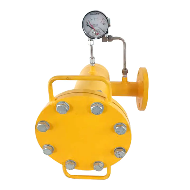

LPG Pressure Regulator Industrial gas pressure regulator is a key device to ensure the safe use of gas. This regulating valve is mainly used to contro...
See Details
The safety valve natural gas pressure regulator is an important device to ensure the safety of gas use. Its main function is to protect the equipment ...
See Details
The natural gas pressure regulating device box and the gas pressure regulating cabinet are key equipment in the gas transmission system, which are mai...
See DetailsThe company is a manufacturer specializing in gas transmission and +distribution equipment and gas pressure regulators. It is a professional manufacturer integrating the research and development, design, manufacturing, marketing and after-sales service of gas equipment.
Phone: +86 138-5131-2088
Tel: +86 0515-83918669
Email: [email protected]
Add: No. 13, Yongchuang Road, Dazhong Industrial Park, Dafeng District, Yancheng City, Jiangsu Province, China
Copyright © Jiangsu Changrun Intelligent Gas Equipment Co., Ltd All Rights Reserved.
Custom Smart Gas Pressure Regulators Manufacturers, Suppliers
![]() Login
Login
Contact Us