 English
 русский
 Español
 عربى
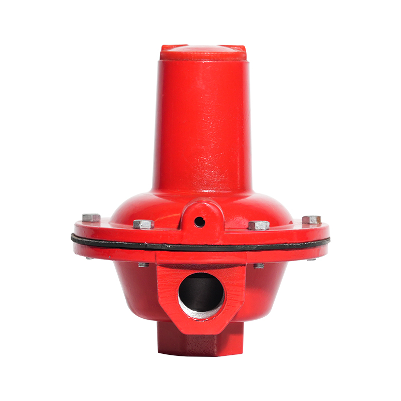
عربىGas automatic relief valve, gas relief valve, safety relief valve
The automatic gas relief valve is a safety device used to adjust the pressure in the gas system to ensure the stable operation of the system. The valv...
See Details

Request a Quote
Content
In the safety operation system of gas systems, automatic relief valves act as “invisible guardians.” Whether it is the gas pipeline in a home kitchen or small industrial gas equipment, potential risks always lurk in the pressure changes within the system. When gas pressure exceeds the safety threshold due to pipeline blockages, sudden temperature rises, or equipment failures during transmission, the absence of a timely pressure relief device could lead to severe accidents such as pipeline bursts, gas leaks, or even explosions. The core function of an automatic gas relief valve lies in its ability to precisely sense pressure changes: it opens automatically when the pressure exceeds the set value, rapidly releases excess gas, and closes once the system pressure returns to a safe range. This closed-loop response of “sensing-action-reset” avoids delays in manual operation and ensures continuous system safety even during unattended operation. Compared to ordinary valves, its sensitivity can reach ±0.05MPa with a response time of less than 1 second, which is why automatic relief valves are mandated as essential safety equipment in various gas system regulations.
The installation environment of home gas systems is relatively narrow and closely linked to daily life, so the installation details of automatic relief valves directly affect usage safety. Before installation, confirm that the valve’s interface specifications match the gas pipeline—household pipelines are usually DN15 or DN20, requiring corresponding relief valve models. The installation location should avoid heat sources and direct sunlight, maintain a horizontal distance of at least 30 centimeters from the gas meter, and ensure sufficient space around the valve for future maintenance. During installation, pay attention to the flow direction mark on the valve body, which must align with the gas flow direction; reverse installation will cause pressure sensing failure. When connecting pipelines, use dedicated sealing materials such as gas-specific PTFE tape, wrapping 3-5 uniform layers around the interface threads to prevent leaks from poor sealing. After installation, close the main gas valve, slowly open the valve for pressure testing, check for abnormal noises or leaks, and put it into use only after confirmation.
Pressure adjustment of gas relief valves is crucial to ensure their precise operation, requiring settings based on the system’s design pressure and actual usage scenarios. Before adjustment, clarify the system’s maximum allowable working pressure—usually 2kPa for household gas systems and 5-10kPa for small industrial systems. During adjustment, first close the shut-off valves before and after the relief valve, loosen the adjustment nut on top of the valve body, and rotate the adjustment screw clockwise to increase the set pressure or counterclockwise to decrease it, with each full rotation corresponding to a pressure change of approximately 0.5kPa. Use a pressure gauge for real-time monitoring during adjustment, and lock the adjustment nut once the pointer stabilizes at the target pressure. Its principle relies on balancing spring force and system pressure: when system pressure exceeds the preset spring force, the valve disc opens to release pressure; when pressure drops, spring force pushes the disc to reset and close. Note that pressure adjustment must be performed by professionals; unauthorized increases may cause valve failure and buried safety hazards.
Small gas systems such as restaurant kitchens and laboratory gas equipment require comprehensive considerations during selection due to high usage frequency and load fluctuations. First, determine the nominal diameter of the relief valve based on the system’s maximum flow rate—DN15 for systems with 1-3m³/h flow and DN20 for 3-6m³/h. Second, focus on the valve’s pressure relief accuracy; for scenarios requiring high pressure stability, choose Class 1 precision products with an error range within ±1% of the set value. Additionally, medium compatibility is critical: for gas with high sulfur content such as artificial gas, select corrosion-resistant stainless steel valve bodies to prevent internal components from jamming due to corrosion. Meanwhile, check the valve’s operating temperature range to ensure it adapts to possible system temperature changes—usually -20℃ to 80℃ suffices for most small systems. Avoid blindly pursuing large displacement during selection, as oversized relief valves may cause sudden pressure drops and affect normal operation.
Automatic gas relief valves may develop various faults during long-term use, and timely troubleshooting is key to ensuring their functionality. Frequent valve opening for pressure relief may indicate persistently high system pressure—first check for pipeline blockages or pressure regulator malfunctions, then recalibrate the relief valve after elimination. If the valve fails to operate, internal valve discs may be stuck by impurities; in this case, close the main gas valve, disassemble the valve body for cleaning, remove dirt from the valve seat and disc, and avoid damaging the sealing surface during reassembly. Another common issue is minor leakage after closing: apply soapy water to the sealing area to check for bubbles. For slight leaks, fine sandpaper can gently polish scratch marks on the sealing surface; severe leaks require replacing the sealing gasket. Abnormal noises during valve operation often result from loose springs or worn components—disassemble, inspect, and replace damaged parts to ensure tight component coordination.
Daily maintenance significantly extends the service life of automatic gas relief valves and reduces faults. Visually inspect the valve weekly, checking for loose connections and signs of corrosion or deformation on the valve body. Conduct a manual pressure relief test monthly by slowly rotating the manual relief lever to observe normal exhaust, then confirm complete valve reset. Calibrate the pressure gauge quarterly to ensure accurate readings and avoid misjudgments due to indicator deviations. For valves used over 1 year, disassemble and clean internal components, especially the sealing surfaces of the valve disc and seat, to remove carbon deposits and impurities; simultaneously check spring elasticity and replace if necessary. For long-term unused systems, close the valves before and after the relief valve, empty internal gas to prevent impurity accumulation. Note that all operations must be performed with the main gas valve closed, and pressurized disassembly is strictly prohibited to ensure safety.

The automatic gas relief valve is a safety device used to adjust the pressure in the gas system to ensure the stable operation of the system. The valv...
See Details
Industrial gas pressure regulating valve pressure reducing valve, pressure stabilizer is a device used to regulate and stabilize gas pressure. It can ...
See Details
The intelligent voltage regulator static characteristic test bench can automatically clamp the voltage regulator to be tested, with high detection acc...
See DetailsThe company is a manufacturer specializing in gas transmission and +distribution equipment and gas pressure regulators. It is a professional manufacturer integrating the research and development, design, manufacturing, marketing and after-sales service of gas equipment.
Phone: +86 138-5131-2088
Tel: +86 0515-83918669
Email: [email protected]
Add: No. 13, Yongchuang Road, Dazhong Industrial Park, Dafeng District, Yancheng City, Jiangsu Province, China
Copyright © Jiangsu Changrun Intelligent Gas Equipment Co., Ltd All Rights Reserved.
Custom Smart Gas Pressure Regulators Manufacturers, Suppliers
![]() Login
Login
Contact Us