 English
 русский
 Español
 عربى
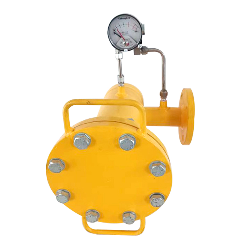
عربىLPG/natural gas/fuel gas filter with differential pressure gauge
The LPG/natural gas/fuel gas filter with differential pressure gauge is a device that filters gas and monitors its pressure changes. The filter can ef...
See Details

Request a Quote
Content
In gas supply systems, ensuring that the delivered gas is free from particulates, dust, condensates or other impurities is crucial for protecting downstream equipment. A fuel gas filter placed upstream of regulators, valves, or burners plays this vital role by capturing solid contaminants. However, as a filter collects debris over time, its internal resistance gradually increases, resulting in a pressure drop between its inlet and outlet. That is where a differential pressure gauge comes into play: it measures the pressure difference across the filter and provides an indicator of how clogged or clean the filter is. By continuously monitoring that differential pressure, operators can judge when maintenance or filter replacement is needed, preventing sudden failures or contamination passage.
The principle behind the differential pressure measurement is elegant yet effective. Two pressure ports—one upstream (high side) and one downstream (low side)—are connected to the gauge. Inside, a sensing element such as a diaphragm, piston, or bellows responds to the pressure difference and displaces proportionally, driving a pointer or a readout display. The magnitude of differential pressure correlates with the resistance introduced by the filter, so as clogging worsens, the differential reading increases. Through calibration and known acceptable thresholds, that value becomes a direct signal for filter condition.
When selecting a fuel gas filter with differential pressure gauge for an LPG or natural gas system, several technical parameters demand careful scrutiny. First, measurement accuracy and resolution are critical: the gauge must resolve small pressure differences (often in tens to hundreds of pascals or inches of water) so that early-stage pressure rise is detectable before the filter becomes fully blocked. Secondly, the range and span of the differential pressure scale should encompass both clean and clogged conditions without saturating the gauge. Third, connection types and sizes must match the piping (for example, threaded, flanged, or compression fittings) and avoid introducing extra flow disturbance. Fourth, material compatibility matters, as LPG and natural gas may carry trace contaminants or moisture; thus, wetted parts should resist corrosion, chemical attack, or degradation over time. Finally, maintenance accessibility and portability influence design: ability to zero the gauge, access to calibration, and space for maintenance without disassembling major piping are practical considerations that can make or break a design in real settings.
Another vital aspect is compatibility across gas types—LPG, natural gas, or mixed fuel gas. Their densities, flow characteristics, and contaminant types may differ. A filter system optimized for LPG (which is heavier, more condensable) might require different pore sizes or media than one for lean natural gas. Also, differential pressure behavior under variable temperature or pressure conditions should be accounted for, ensuring accurate readings across the operational envelope.
Proper installation is essential to ensure the differential pressure gauge produces meaningful data. The pressure taps upstream and downstream of the filter must be placed at points where the flow is fully developed and free from obstructions such as sudden bends, valves, or other flow-disturbing elements. Ideally, the taps are placed a few pipe diameters upstream and downstream to allow stable readings. The gauge itself should be installed at a position where it is not subject to vibration, shock, or extreme temperature swings, and where operators can easily read or service it. Ensuring the gauge is mounted at the proper orientation so that gravity does not bias the sensing element is important—some gauges allow flexible orientation, but zeroing or calibration must account for that.
Before commissioning, a zero-point calibration (or zero adjust) must be performed when the filter is new and clean, to ensure that the baseline differential is set to zero or near-zero. Periodic checks are also needed, especially after maintenance or replacement of filter elements. The installation should also allow for sufficient clearance around the gauge for future access, calibration tools, and possible replacement, without requiring pipeline removal. For systems with multiple filters in parallel, a manifold or bypass arrangement may be included to allow filter replacement without system shutdown, and the gauge readings can drive which filter is active.
Once installed, the differential pressure gauge becomes a real-time window into filter health. As gas passes through the filter, the differential pressure is low in a clean state. Over time, as debris accumulates, the pressure differential gradually increases. By observing this rising trend, operators can schedule maintenance before the filter becomes fully clogged and causes undue pressure drop or allows contaminants through. A sudden jump in differential pressure may indicate unusual particulate influx or damage. Setting alarm thresholds is standard practice: for example, a warning level at, say, 50% of full scale, and a critical level near 80 – 90% of full scale, triggering alerts or even automatic valve actuation to isolate or bypass the filter.
In more sophisticated systems, the gauge’s output can feed into a control system to trigger automatic filter bypass or switching in multi-filter arrangements. That ensures continuity of gas supply while maintenance occurs. The gauge might also interface with remote monitoring systems or SCADA to log historical differential pressure trends, which help in predictive maintenance and lifetime estimation of filter media. By diagnosing accelerated differential pressure rise, engineers can deduce changes in upstream contamination levels, gas quality deterioration, or upstream process deviations.
Consider a mid-pressure gas regulation and metering station serving an industrial facility. In such a station, upstream gas is cleaned by a filter equipped with a differential pressure gauge before entering a pressure reduction train. The filter sits ahead of regulators and safety valves. With the gauge in place, the station operator monitors the differential pressure over weeks or months. As the facility’s demand rises, increased gas flow causes slightly faster accumulation of contaminants, and the differential pressure increment becomes noticeable. When the gauge reading approaches the warning threshold, a maintenance window is scheduled to change the filter element. Without the gauge, operators might either guess maintenance intervals (risking premature clogging or contamination breach) or replace filters too frequently (wasting media). In practice, the gauge prevents unplanned downtime and protects the expensive regulators downstream.
In another scenario, in a gas-fired boiler application within a chemical plant, the gas supply line uses this filter plus differential pressure gauge arrangement. During a process upset upstream, contaminants spike temporarily, and the gauge reading shows a rapid rise. The control system senses this and switches to a parallel filter train while personnel replace the clogged unit. Thanks to real-time monitoring, boiler performance remains stable without manual intervention or shutdown.
Looking forward, the evolution of fuel gas filters with differential pressure gauges is heading toward smart instrumentation. That includes integrating digital sensors that provide 4-20 mA or digital bus outputs (e.g. HART, Modbus) rather than analog pointers, enabling remote monitoring, diagnostics, and integration into IoT systems. This allows continuous data logging, trend analysis, and alerting from centralized control rooms. Another trend involves self-cleaning filter media or backwash systems where the gauge reading actively drives cleaning cycles, reducing manual maintenance. On the materials front, advanced coatings, corrosion-resistant alloys, and more robust sealing can improve longevity in harsh or corrosive gas streams.
Finally, miniaturization and compact modular designs are in demand—smaller footprints, fewer dead volumes, and simplified maintenance are desirable in tight installations. Combined with better sensor algorithms and self-diagnostics (e.g. detecting sensor drift or leaks), the next generation of filters with differential pressure gauges will deliver more reliability, lower total cost of ownership, and higher operational safety in LPG and natural gas installations.
The LPG/natural gas/fuel gas filter with differential pressure gauge is a device that filters gas and monitors its pressure changes. The filter can ef...
See Details
Industrial gas pressure regulating valve pressure reducing valve, pressure stabilizer is a device used to regulate and stabilize gas pressure. It can ...
See Details
X-ray flaw detection room is a place specially used for X-ray flaw detection. It is equipped with X-ray industrial flaw detectors for non-destructive ...
See DetailsThe company is a manufacturer specializing in gas transmission and +distribution equipment and gas pressure regulators. It is a professional manufacturer integrating the research and development, design, manufacturing, marketing and after-sales service of gas equipment.
Phone: +86 138-5131-2088
Tel: +86 0515-83918669
Email: [email protected]
Add: No. 13, Yongchuang Road, Dazhong Industrial Park, Dafeng District, Yancheng City, Jiangsu Province, China
Copyright © Jiangsu Changrun Intelligent Gas Equipment Co., Ltd All Rights Reserved.
Custom Smart Gas Pressure Regulators Manufacturers, Suppliers
![]() Login
Login
Contact Us