 English
 русский
 Español
 عربى
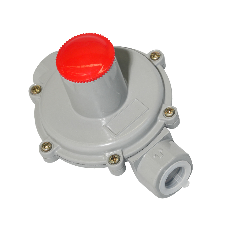
عربىGas automatic relief valve, gas relief valve, safety relief valve
The automatic gas relief valve is a safety device used to adjust the pressure in the gas system to ensure the stable operation of the system. The valv...
See Details

Request a Quote
Content
The regulation of natural gas pressure is an intricate process designed to safely deliver fuel from high-pressure transmission lines to end-use appliances, which operate at significantly lower pressures. This critical pressure reduction is managed by sophisticated regulators, yet their failure, though rare, poses a serious systemic risk. Exploring Overpressure Risks from Regulator Failure involves recognizing scenarios where the main regulator element, such as the diaphragm or valve seat, could fail to fully close, allowing high upstream pressure to overwhelm the lower-pressure downstream system. This can occur due to foreign debris lodging in the valve seat, internal mechanical component fatigue, or a sudden, uncontrolled surge from the supply side. An overpressurization event beyond the system's maximum allowable operating pressure (MAOP) can lead to catastrophic damage to pipework, connections, and sensitive end-user equipment, creating the substantial risk of gas leaks, fire, and explosion. The potential consequences mandate the incorporation of secondary safety measures. The Necessity and Core Principles of Overpressure Protection therefore revolve around redundancy and containment. The primary principle dictates that the downstream system must be safeguarded against pressures exceeding a safe, predetermined limit, ensuring that even in the complete failure of the primary regulator, the integrity of the downstream infrastructure remains intact. These protective layers act as a final barrier to mitigate hazards and maintain continuous, safe operation.
Multiple, complementary devices and configurations are utilized to achieve robust overpressure protection. Relief Valve Functionality and Application constitutes one of the most common and direct methods. A relief valve is a spring-loaded device that is set to open and vent gas to the atmosphere when the downstream pressure reaches a specific, elevated setpoint. This action immediately relieves the excess pressure, preventing it from continuing to build within the confined space of the pipeline. They are typically employed in systems where the volume of relieved gas can be safely dispersed without hazard, such as smaller systems or those in remote locations. Conversely, the Preventative Role of the Slam-Shut Valve offers a containment strategy. This device is an automatic shutoff valve installed upstream or integrated within the main regulator body, engineered to rapidly and completely close the gas flow when the downstream pressure exceeds a preset high-limit threshold. Unlike a relief valve which vents gas, the slam-shut valve isolates the downstream system entirely, halting the supply of gas until the condition is manually investigated and reset. For larger, more critical gas distribution points, the practice of Combined Protection with Series Regulation and Monitors is frequently adopted. Series regulation involves installing two regulators in succession, where the first, or "worker," does the primary pressure reduction, and the second, or "monitor," is set to take over if the worker fails open. This containment method ensures that a secondary device is always ready to assume control, maintaining the pressure below the maximum safe level without venting any gas.
The efficacy of any overpressure protection system is fundamentally tied to the correct selection and installation of its components. Factors in Correctly Sizing a Natural Gas Relief Valve are highly technical and include calculating the maximum potential inlet pressure, the required setpoint for the relief, and the full flow capacity of the system should the main regulator fail wide open. The relief valve must possess a large enough orifice to adequately discharge the entire possible maximum flow rate of gas, ensuring that the pressure inside the system does not continue to climb even while the valve is actively venting. An undersized relief valve will prove ineffective during a full failure scenario. Furthermore, the installation location is paramount, especially for residential and commercial sites. The Importance of the Vent Line for Residential Safety cannot be overstated. All relief valves must vent their discharged gas to a safe outdoor location, away from windows, doors, air intakes, and any potential ignition sources. The vent line must be appropriately sized to prevent back-pressure from building up and hindering the relief valve's operation, which is a critical safety factor ensuring that the relieved gas safely dissipates into the atmosphere, rather than accumulating dangerously near a building structure.
While the terms "relief valve" and "safety valve" are often used interchangeably in general discourse, there are technical distinctions that are crucial in industrial and regulatory contexts. Distinguishing Functions, Operations, and Reset Methods lies in the nature of their opening. Technically, a relief valve is designed to open proportionally to the increase in pressure over its setpoint, whereas a true safety valve is characterized by its rapid, full-opening or "pop" action once the pressure setpoint is reached. Furthermore, some safety shutoff valves, like the slam-shut type, require a manual reset after actuation, ensuring human inspection of the failure cause. Relief valves often close automatically once the pressure drops back below the setpoint. These differences reflect their Different Roles in Various Application Settings. Relief valves are frequently used to protect equipment from simple overloads in liquid or gas service. Safety shutoff mechanisms, however, are mandatory for protecting life and property against catastrophic high-pressure excursions in high-hazard gaseous systems, such as natural gas distribution mains, where the abrupt and complete cessation of flow is the ultimate protective measure.
Long-term reliability of the overpressure protection system hinges on rigorous maintenance and a systematic approach to troubleshooting. A common issue encountered is the Troubleshooting Steps for Internal Relief Valve Leaks. A persistent low-level leak, often indicated by a continuous, faint hissing sound at the vent line, suggests that the internal relief valve, integrated into the regulator body, is not seating correctly. Initial steps involve checking the regulator's downstream pressure to confirm it is not running high, which would naturally keep the relief valve partially open. If the pressure is nominal, the leak is likely caused by foreign particles obstructing the valve's seal, requiring the regulator to be depressurized, disassembled, and the valve seat to be thoroughly cleaned or replaced. Finally, Maintenance Essentials for Long-Term Performance and System Reliability must include periodic operational checks of the relief and slam-shut mechanisms. This preventative testing ensures the valves can open or close at their designated setpoints and that the associated components, such as diaphragms and springs, have not degraded. Regular inspections of the vent line integrity—checking for blockages, insect nests, or proper termination—are equally vital to guarantee that the entire safety chain remains fully functional when it is most needed.

The automatic gas relief valve is a safety device used to adjust the pressure in the gas system to ensure the stable operation of the system. The valv...
See Details
Safety valve gas control pump accessories pressure regulator is a key component in the gas supply system. Its main function is to ensure the stable su...
See Details
The film test high and low temperature chamber is a device specially used to test the stability and reliability of material films under different temp...
See DetailsThe company is a manufacturer specializing in gas transmission and +distribution equipment and gas pressure regulators. It is a professional manufacturer integrating the research and development, design, manufacturing, marketing and after-sales service of gas equipment.
Phone: +86 138-5131-2088
Tel: +86 0515-83918669
Email: [email protected]
Add: No. 13, Yongchuang Road, Dazhong Industrial Park, Dafeng District, Yancheng City, Jiangsu Province, China
Copyright © Jiangsu Changrun Intelligent Gas Equipment Co., Ltd All Rights Reserved.
Custom Smart Gas Pressure Regulators Manufacturers, Suppliers
![]() Login
Login
Contact Us