 English
 русский
 Español
 عربى
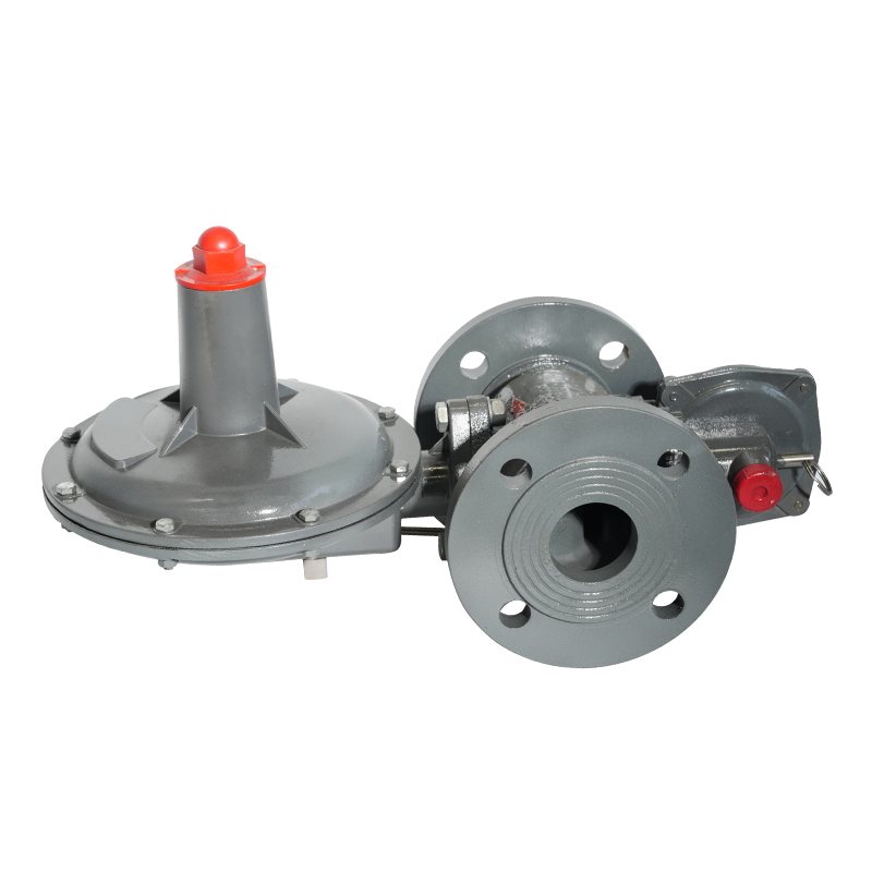
عربىGas automatic relief valve, gas relief valve, safety relief valve
The automatic gas relief valve is a safety device used to adjust the pressure in the gas system to ensure the stable operation of the system. The valv...
See Details

Request a Quote
Content
In natural gas distribution systems, pressure management is not optional. It is a fundamental engineering requirement. A gas pressure regulating box is a pre-assembled enclosure that houses pressure regulation components, safety devices, and metering interfaces in a single protected unit. It accepts high-pressure gas from the supply main and delivers it at a stable, lower pressure to end-use equipment. For procurement managers, contractors, and system engineers, understanding this device at a technical level is essential for correct specification and long-term system reliability.
The primary task of a gas pressure regulating box is to reduce and stabilize upstream supply pressure to a predetermined downstream delivery pressure. Upstream pressures in medium-pressure urban distribution networks typically range from 0.1 MPa to 0.4 MPa. Residential end-use equipment commonly requires a delivery pressure between 1,000 Pa and 3,000 Pa. The regulating box must bridge this differential safely and continuously under variable flow conditions.
The regulator inside the enclosure uses a diaphragm-and-spring mechanism. When downstream demand increases, the diaphragm deflects and opens the valve seat, allowing more gas to pass. When demand decreases, the spring force closes the valve seat. This feedback loop maintains outlet pressure within a defined tolerance band, typically plus or minus 5 percent of the set point, as specified in EN 334 for gas pressure regulators.
A fully configured unit integrates multiple functional elements. Each component serves a defined role in pressure control, safety, and monitoring. The typical assembly includes the following:
The table below maps each major component to its engineering function and the relevant performance standard commonly referenced in procurement specifications.
| Component | Function | Reference Standard |
|---|---|---|
| Inlet ball valve | Manual upstream isolation | EN 331 / ASME B16.34 |
| Filter/strainer | Particulate removal (50 micron) | EN 14382 |
| Pressure regulator | Pressure reduction and stabilization | EN 334 / ANSI Z21.80 |
| Slam-shut valve | Automatic over/under-pressure shutdown | EN 14382 |
| Relief valve | Over-pressure venting to the atmosphere | EN 12263 |
| Pressure gauge | Inlet and outlet pressure monitoring | EN 837-1 |
| Outlet ball valve | Downstream isolation | EN 331 / ASME B16.34 |
These two terms are sometimes used interchangeably in non-technical purchasing documents, but they describe different levels of assembly. A pressure-reducing valve (PRV) is a single-line device. A gas pressure regulating box is a complete system that incorporates a PRV along with safety, isolation, and monitoring components inside a weather-resistant enclosure. The differences are significant for system design and regulatory compliance.
| Feature | Gas Pressure Regulating Box | Pressure Reducing Valve (standalone) |
|---|---|---|
| Safety devices included | SSV, relief valve, filter | None (separate installation required) |
| Enclosure protection | IP44 to IP65 rated cabinet | No enclosure |
| Installation footprint | Single wall-mounted or buried unit | Inline pipe assembly |
| Regulatory compliance | Pre-certified as an assembly | Requires field-assembled certification |
| Maintenance access | Single enclosure, all components accessible | Distributed across the pipeline |
| Typical application | Building entry, district regulation stations | Appliance-level pressure adjustment |
The enclosure body is typically fabricated from galvanized steel, stainless steel, or fiberglass-reinforced polyester (FRP). Material selection depends on the installation environment, burial depth, and expected service life.
An outdoor gas pressure regulating box enclosure must satisfy several simultaneous requirements. It must resist mechanical impact, moisture ingress, UV degradation, and thermal cycling. In most European markets, enclosures must meet at a minimum IP44 protection class per IEC 60529. Underground or semi-buried models require IP67 or higher. In North American markets, NEMA 3R or NEMA 4X ratings govern equivalent protection levels. Ventilation openings must be sized to prevent hazardous gas accumulation while excluding insects and water. Lockable doors are mandatory in most utility and industrial codes.
A gas pressure regulating box for natural gas serves different system roles depending on the pressure tier and the volume of gas being delivered.
At the building entry point, a compact unit typically handles flow rates from 6 m3/h to 25 m3/h and reduces medium-pressure supply (0.1 to 0.4 MPa) to low-pressure distribution (2,000 Pa). These units are mounted on exterior walls or set into ground-level niches. They must comply with local gas safety regulations such as EN 12007-3 in Europe or NFPA 54 in North America.
Larger district regulation stations handle flows exceeding 500 m3/h and may incorporate dual-train redundancy, telemetry modules, and heated enclosures for cold-climate operation. These systems connect to SCADA networks and provide continuous pressure and flow data to network control centers.
Correct installation determines both safety performance and service life. The following requirements apply across most regulatory frameworks and should be verified against the local gas authority's technical code before final procurement:
For distributors and contractors sourcing at volume, the following technical criteria should appear in every request for quotation (RFQ) or purchase specification:
Most residential and commercial units accept inlet pressures from 0.01 MPa to 0.4 MPa and deliver outlet pressures between 1,000 Pa and 10,000 Pa. Industrial units can handle inlet pressures up to 1.6 MPa or higher. The specific pressure class is stamped on the regulator nameplate and must match the pipeline design pressure. Always verify the maximum allowable operating pressure before installation.
Most utility and industrial codes require annual inspection of the slam-shut valve and relief valve function. Filter elements should be inspected every 12 months and replaced when the pressure drop across the filter exceeds 0.5 kPa under normal flow conditions. Full servicing, including diaphragm and seat inspection, is typically scheduled every 3 to 5 years, depending on gas quality and operating hours.
In a monitor configuration, two regulators are installed in series. The upstream unit (monitor) is set slightly above the working set point. Under normal conditions, the downstream active regulator controls pressure. If the active regulator fails open, the monitor takes over automatically, preventing over-pressurization of the downstream system. This configuration is required in many utility codes for medium-to-high pressure district stations.
Yes. Units designed for natural gas service can often be adapted for liquefied petroleum gas (LPG), biogas, and other non-corrosive fuel gases by changing internal elastomers and spring sets. However, the original certification applies only to the gas type specified on the nameplate. Using a unit outside its certified gas type without re-certification is a regulatory violation in most jurisdictions. Always confirm material compatibility and re-certify if the gas composition changes.

The automatic gas relief valve is a safety device used to adjust the pressure in the gas system to ensure the stable operation of the system. The valv...
See Details
Natural gas pressure regulating box, wall-mounted building pressure regulating box is a key equipment of gas transmission pipeline. Its main function ...
See Details
The leveling laser cutting machine is an advanced device that combines the leveling and laser cutting functions. It uses a high-precision laser beam f...
See DetailsThe company is a manufacturer specializing in gas transmission and +distribution equipment and gas pressure regulators. It is a professional manufacturer integrating the research and development, design, manufacturing, marketing and after-sales service of gas equipment.
Phone: +86 138-5131-2088
Tel: +86 0515-83918669
Email: [email protected]
Add: No. 13, Yongchuang Road, Dazhong Industrial Park, Dafeng District, Yancheng City, Jiangsu Province, China
Copyright © Jiangsu Changrun Intelligent Gas Equipment Co., Ltd All Rights Reserved.
Custom Smart Gas Pressure Regulators Manufacturers, Suppliers
![]() Login
Login
Contact Us