 English
 русский
 Español
 عربى
عربىPN16 DN50/DN80 flanged ductile iron Y-type strainer
PN16 DN50/DN80 flange ductile iron Y-type filter valve is a flange-connected ductile iron Y-type filter valve. PN16 means the nominal pressure is 1.6M...
See Details


Request a Quote
Content
A city gate station can take natural gas in at 4.0 MPa and hand it down, three stages later, at roughly 2 kPa outside a household meter - a pressure ratio close to 2,000 to 1, achieved with no pump, no motor and no external control loop. The device doing that work is the natural gas pressure regulator, and it runs on the line gas itself. Its failure mode is quiet: a drifting set point or a badly sized seat rarely triggers an alarm this week, but it surfaces months later as unstable burner output, nuisance shutdowns or a valve that freezes in the first cold snap. This guide sets out the four specifications that decide sizing, why oversizing causes more trouble than undersizing, and the three field conditions that most often end a regulator's service life early.
A natural gas pressure regulator is a self-powered feedback device: downstream gas pushes on a diaphragm, the diaphragm repositions the valve orifice, and the mechanism settles exactly where gas supply matches downstream demand.
Definition: a natural gas pressure regulator is a mechanically loaded control valve that reduces a higher, variable inlet pressure to a lower, steady outlet pressure and corrects itself automatically, without any external power source.
Because the gas itself supplies the operating energy, regulation continues through power failures and stations can run unattended. A loading spring or dome sets the target; a sensing line feeds downstream pressure back under the diaphragm. When demand rises and outlet pressure dips, the orifice opens; when demand collapses toward zero, the valve travels toward lockup and shuts the line tight. How well a design holds its set point across the flow range is published as an accuracy class: under EN 334, an AC5 regulator keeps outlet pressure within 5 percent of set point from minimum to maximum rated flow, while an AC2.5 unit holds it within 2.5 percent. For a component-level walkthrough of the diaphragm, orifice and loading mechanism, see this explanation of how a gas pressure regulator works.
Four numbers decide whether a regulator survives contact with your station: maximum inlet pressure, outlet set point with its accuracy class, the full flow range, and lockup class. Everything else on the datasheet is detail.
| Specification | Confirm with the supplier | Common mistake |
| Maximum inlet pressure | The highest pressure the upstream line can deliver, including upset and testing conditions | Rating the valve to normal operating pressure only |
| Outlet set point and accuracy class | An exact set point plus the class required; AC5 or tighter for burner trains | Asking for pressure as low as possible instead of a number |
| Flow range, minimum to maximum | Winter minimum load, peak load and planned expansion | Sizing to peak flow and ignoring night-time minimum load |
| Lockup class | How far outlet pressure may rise at zero flow, per the lockup pressure class | Assuming lockup pressure equals the set point |
Give the supplier both ends of the load curve, not just the peak. A valve whose peak load sits at 95 percent of rated capacity will spend every night throttling nearly closed, where control is nonlinear and seat wear accelerates.
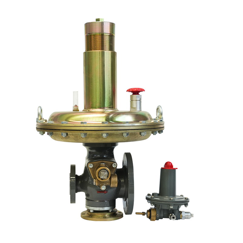 Pipeline Gas Pressure Reducing Valve and RegulatorAvailable in multiple capacities and accuracy classes, this pipeline regulator suits stations where correctly matched valve sizing prevents hunting, seat wear and droop across both peak and low demand.View Product →
An oversized regulator is not a safety margin; in industrial service it is the most common root cause of unstable outlet pressure. When peak load uses only a small share of a valve's capacity, the seat operates nearly closed for most of its life. At low demand the diaphragm hunts between open and shut; at peak demand the same valve squeezes gas through a small effective opening, and droop pushes outlet pressure out of class.
Oversized unit
Right-sized unit
Outlet pressure versus flow for a right-sized and an oversized natural gas pressure regulator. The shaded band is the EN 334 AC5 tolerance; the dashed curve leaves it before peak load.
If maximum load divided by minimum load exceeds roughly 10 to 1, one valve rarely covers the range. The standard answers are a wide-set and a narrow-set regulator in parallel, or cascaded stages, so each unit always works inside its controllable window.
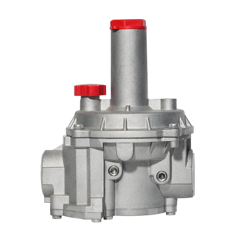 Industrial Gas Pressure Regulator and Reducing ValveFor load ranges wider than one valve can cover, this industrial LPG and natural gas regulator supports parallel wide-set and narrow-set configurations, keeping each unit within its controllable window.View Product →
Three conditions shorten regulator life in the field, and none of them appears on the datasheet: cold gas, dirty gas and overpressure events.
Gas cools as it expands, and natural gas loses roughly 0.5 degrees Celsius per bar of pressure drop. A single stage from 16 bar to 2 bar can chill the gas by about 7 degrees Celsius, enough to condense moisture and form hydrates that ice the valve internally. Multi-stage reduction, dry gas quality and heat input upstream of the valve are the practical counters, and outdoor regulators in cold climates should be specified for exactly this duty.
Mill scale, pipe dope and sand from new pipelines destroy seats and pilot passages long before diaphragms age out. A filter or Y-strainer upstream of the regulator is standard practice, and a differential pressure gauge across the element turns it into a monitored device rather than a guess.
A differential pressure gauge on the upstream filter is the cheapest early-warning instrument in the station: when the reading climbs, contamination is moving toward the regulator seat, not away from it.
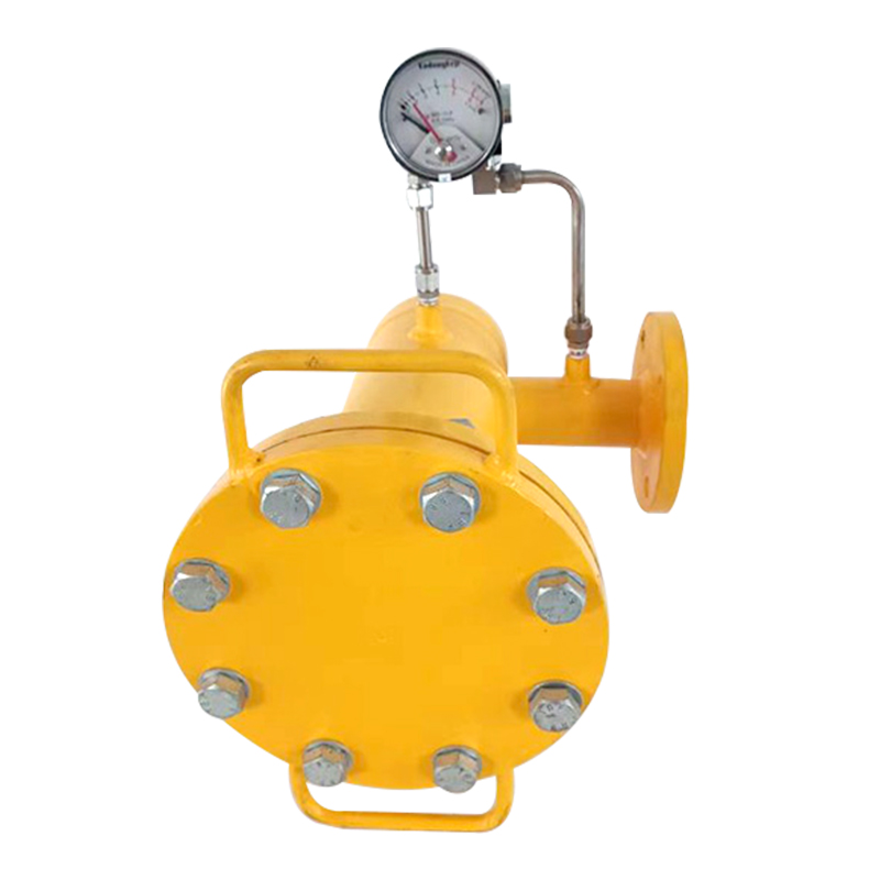 LPG and Natural Gas Filter with Differential Pressure GaugeA differential pressure gauge on the upstream filter gives the earliest warning that contamination is approaching the regulator seat, so clogging can be addressed before outlet pressure stability suffers.View Product →
If downstream equipment is rated below the maximum inlet pressure, station design must assume the regulator can fail open. That means a slam-shut safety shutoff triggered by outlet overpressure, plus a relief path sized for the regulator's wide-open capacity. Relief valves and slam-shut units are ordered together with the regulator, not retrofitted after commissioning.
A disciplined selection meeting covers five steps, and the first two decide most of the outcome.
Write the pressure envelope. Record maximum and minimum inlet pressure, the exact outlet set point, and any test-pressure conditions the valve must survive.
Tabulate the load. List winter minimum flow, peak flow and expansion plans; these two numbers define the sizing window.
Choose the classes. Fix the accuracy class and lockup class in writing; AC5 suits most burner trains, AC2.5 suits tight process loads.
Add the protection chain. Filter with differential pressure gauge upstream, slam-shut and relief capacity downstream, and sampling points for verification.
Demand test evidence. Ask how the design is verified: at Jiangsu Changrun Intelligent Gas Equipment Co., Ltd., regulator production is backed by a dedicated static characteristics test bench, spring testing machines and X-ray weld inspection.
The terms overlap heavily, and suppliers use them interchangeably for the same hardware. Pressure reducing valve describes the function of lowering pressure; natural gas pressure regulator adds the expectation of automatic control, meaning it holds a set outlet pressure while inlet pressure and demand vary.
Plan on at least one inspection per year, and always after upstream pipeline work. A typical check verifies set point and lockup, examines the diaphragm and seat for wear, and records the filter differential pressure trend.
Not in a properly designed station. Very large single-stage drops create noise, vibration and severe Joule-Thomson cooling, so stations cascade the reduction through two or more stages, each specified for its own inlet range.
AC5 is a workable baseline for most industrial burners. Equipment that maintains a tight air-to-fuel ratio, such as process burners and some turbines, justifies AC2.5, and the cost difference at selection time is small compared with rework later.
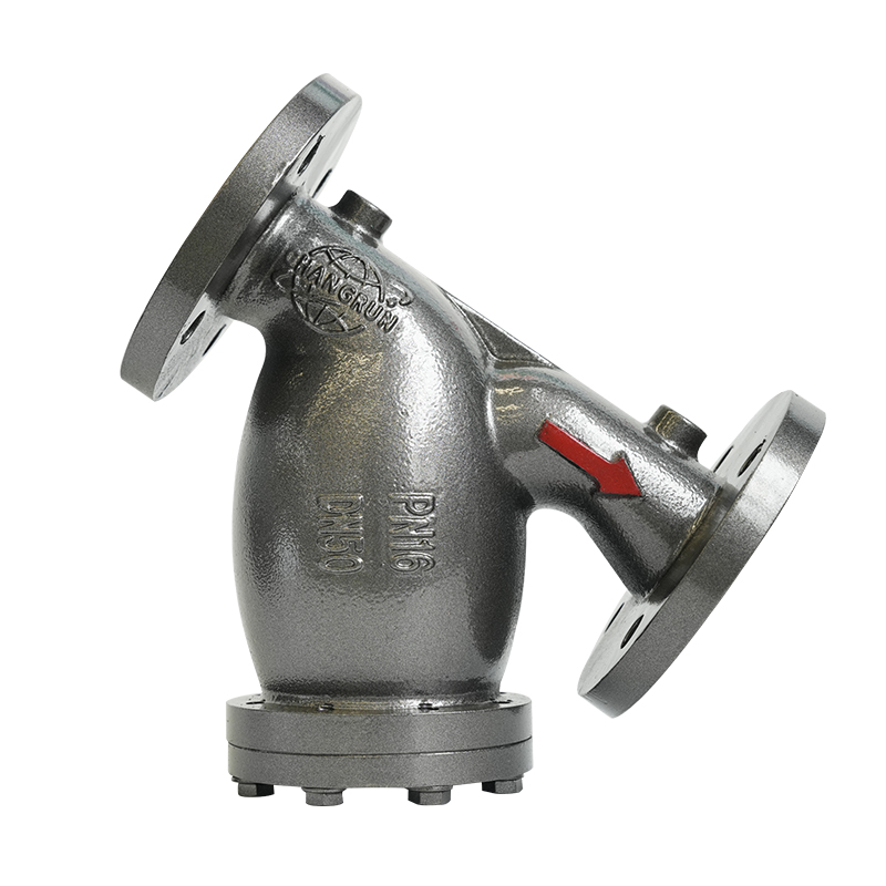
PN16 DN50/DN80 flange ductile iron Y-type filter valve is a flange-connected ductile iron Y-type filter valve. PN16 means the nominal pressure is 1.6M...
See Details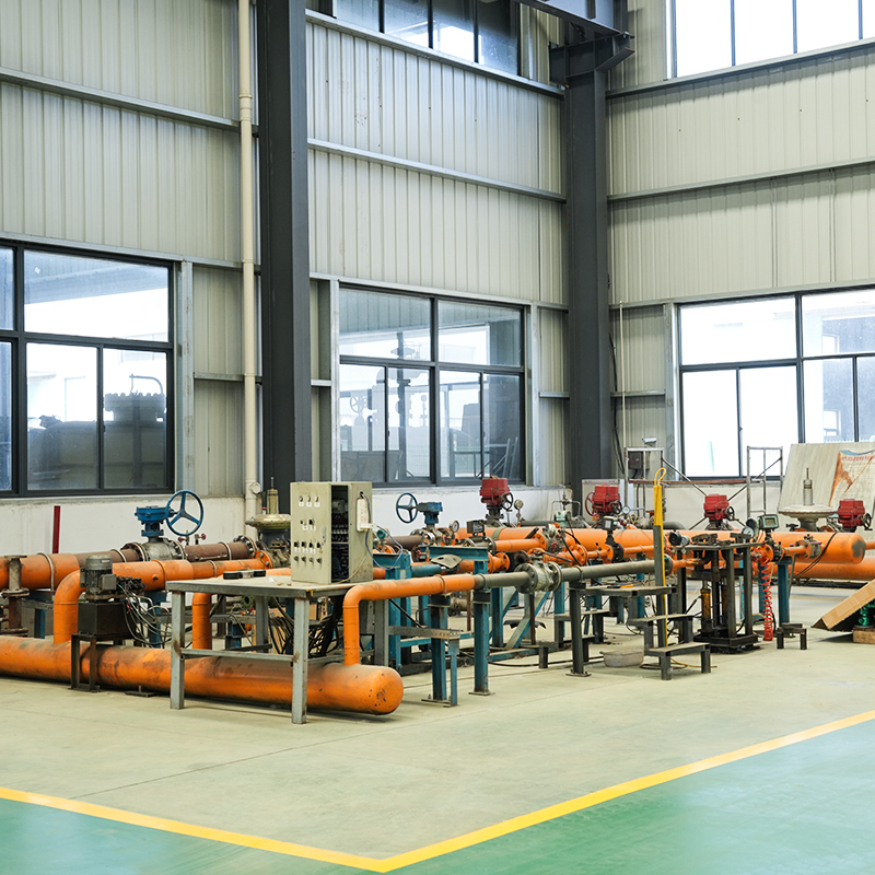
The intelligent voltage regulator static characteristic test bench can automatically clamp the voltage regulator to be tested, with high detection acc...
See Details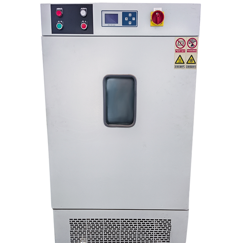
The film test high and low temperature chamber is a device specially used to test the stability and reliability of material films under different temp...
See Details
The company is a manufacturer specializing in gas transmission and +distribution equipment and gas pressure regulators. It is a professional manufacturer integrating the research and development, design, manufacturing, marketing and after-sales service of gas equipment.
Phone: +86 138-5131-2088
Tel: +86 0515-83918669
Email: [email protected]
Add: No. 13, Yongchuang Road, Dazhong Industrial Park, Dafeng District, Yancheng City, Jiangsu Province, China
Copyright © Jiangsu Changrun Intelligent Gas Equipment Co., Ltd All Rights Reserved.
Custom Smart Gas Pressure Regulators Manufacturers, Suppliers
 Login
Login
Contact Us